
Relative Scuffing Load Carrying Capacity Tester, FZG
Brand KN
Product origin DALIAN
Delivery time 30 DAYS AFTER RECEIVING FULL PAYMENT
Supply capacity 30 sets/month
KN-FZG Relative Scuffing Load Carrying Capacity Tester conforms to ISO 14635-1 Gears – FZG test procedures—Part 1: FZG test method A/8, 3/90 for relative scuffing load-carrying capacity of oils and ISO 14635-2 – FZG test method A10/16,6R/90 for relative scuffing load-carrying capacity of lubricants with high EP performance. The types of gear failures which may be influenced by the lubricant in use are scuffing, low-speed wear and the gear-surface fatigue phenomena known as micropitting and pitting. In the gear design process, these gear damages are taken into consideration by the use of specific lubricant and service-related characteristic values. For an accurate, field-related selection of these values, adequate lubricant test procedures are required. The FZG test procedures described in this and other parts of ISO 14635 can be regarded as tools for the determination of the lubricant-related characteristic values to be introduced into the load-carrying capacity calculation of gears.
KN-FZG Relative Scuffing Load Carrying Capacity Tester
Overview
KN-FZG Relative Scuffing Load Carrying Capacity Tester conforms to ISO 14635-1 Gears – FZG test procedures—Part 1: FZG test method A/8, 3/90 for relative scuffing load-carrying capacity of oils and ISO 14635-2 – FZG test method A10/16,6R/90 for relative scuffing load-carrying capacity of lubricants with high EP performance. The types of gear failures which may be influenced by the lubricant in use are scuffing, low-speed wear and the gear-surface fatigue phenomena known as micropitting and pitting. In the gear design process, these gear damages are taken into consideration by the use of specific lubricant and service-related characteristic values. For an accurate, field-related selection of these values, adequate lubricant test procedures are required. The FZG test procedures described in this and other parts of ISO 14635 can be regarded as tools for the determination of the lubricant-related characteristic values to be introduced into the load-carrying capacity calculation of gears.
FZG test method A/8, 3/90 for the relative scuffing load-carrying capacity of oils described in this part of ISO 14635 is typical for the majority of applications in industrial and marine gears. ISO 14635-2 will be related to the relative scuffing load-carrying capacity of oils of very high EP properties, as used for the lubrication of automotive driveline components.
Features & Functions (see Fig.1)
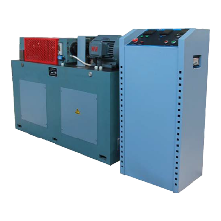
The tester contains the main host and the electric control cabinet, and the two parts are separate.
The main host adopts a dynamic closed-loop structure (or power flow closed structure), and the loading method adopts the method of hanging weights on the loading rod.
The main host is a horizontal structure and should be placed on a level ground. The lower part is the machine base. The upper plane of the base equipped with two gear cases. In the middle of the two gear ceases are two sets of parallel rotating shafts and torsion shafts, as well as a loading clutch and a torque measuring clutch. The left one is the test gear case. A pair of high-precision test gears of different sizes are installed in the case. The left case cover and top cover of the test gear case can be opened to facilitate loading and unloading of the test gears. The right is the transmission gear case, and a pair of high-precision transmission gears of different sizes are also installed in the case. Each gear is mounted on a different shaft in the form of key joint, and each shaft where the gear is mounted is supported by two pairs of deep groove ball bearings and mounted on the left and right gearboxes, on the right side of the transmission gearbox. It is the driving motor of the testing machine, with compact structure, high precision and stable performance.

Fig.1 Loading Device
1. Small test gear 2. Big test gear 3. Transmission gear case 4. Loading clutch
5. Fixed pin 6. Lever arm with weights 7. Torque measuring clutch 8. Temperature sensor
Loading method, see Fig.1
The loading rod is hung on the sheave of the loading clutch. After adding weights, tighten the two sheaves on the loading clutch by tightening the nut of the loading clutch, then, remove the weights and the loading rod. The torque value can be read out on the torque measuring clutch.

Fig.2 Transmission
The drive motor YD132M-4/2 is a two-speed motor, which drives the transmission gear through the shaft to transmit the torque to the test gear. The test gear is in a test gear case, which can contain different liquid test medium, and the test gear part is immersed in the test medium for testing.
Electric cabinet and control panel
The electric control cabinet has four parts, namely the control cabinet body, the control panel, the strong current system and the weak current system. Taking the control cabinet as the structural frame, the control panel above the cabinet is easy to operate, and the inside of the cabinet is equipped with a strong current system. There is a rear door of the control cabinet, and the internal system of the control cabinet can be seen by opening the door, which is convenient for installation, debugging and maintenance.
The control panel has three parts, namely upper, middle and lower parts, as shown in Fig.3. The lower part of the panel is the control switch and alarm. In the middle of the panel are heating, cooling and motor speed selection switches. The upper part of the panel is equipped with temperature controller, time controller and revolution controller. The time display and control unit can select the control time within the range of 1s~9999min. There is a CLEAR button below the control unit, which can clear the digital display window.
The number of revolutions display and control unit can select the control revolution speed in the range of 1~99999999.

Fig.3 Electric cabinet and control panel
Torque measuring clutch
The torque measurement clutch device is shown in Fig.4, which mainly includes: small connecting flange (1), large connecting flange (2), torque shaft (3) inside the outer tube (4), indicating flange (5) with Vernier caliper scale (6) and scale (7) on the large connecting flange (2). After loading, the elastic shaft (3) in the closed-loop system of the tester is twisted and deformed, and the "torque" can be read out through the vernier caliper.

Fig.4 Torque measuring clutch
1. Small flange 2. Big flange 3. Torsion bar 4. Outer tube 5. Indicating flange with vernier caliper
6. Vernier caliper 7. Scale

Fig.5 Gear tooth broken control element
This tester has the gear tooth broken control device, see Fig.5
During the test, if the gear is broken or the load on the gear increases abnormally, the overload automatic protection device will automatically stop the test.
The protection device includes Copper ring (a), flat spring (b), shear sheet (c), pinhole (d) and shear pin (e).
The copper ring (a) is mounted on the bottom plate of the testing machine, but it is insulated from the bottom plate of the testing machine. After loading, adjust the position of the pinhole on the groove of the torque measuring clutch (B), so that it is fixed in the appropriate position corresponding to the shear hole (d). In this position, the shear pin can pass through the shear plate and pinhole. While doing this work, press down the flat spring (b) with the needle (the flat spring is out of the copper ring) and hold the shear pin in place with the screw (f).
If the torque changes abnormally, the indicating flange (5) and the large flange on the torque measuring clutch will rotate relative to each other, thus shearing the shearing needle, the flat spring (b) immediately hits the copper ring (a) and closes A contact of the control circuit is opened, and the drive motor stops immediately.
Main technical parameters
1. Maximum torque: 1k.Nm
2. Maximum load class: Grade 13
3. Temperature accuracy: ±2℃
4. Drive motor power: 6.5kW (8kW)
5. Revolution speed: 1450rpm / 2880rpm
6. Test gear case capacity: 1.25L (The part from the center line of the shaft to the bottom of the case)
7. Heating power: 0.5kW*3=1.5kW
8. Test time control range: 1s~9999min
9. The number of revolution range: 9999999
10. Main host Dimension: 1390*750*1082mm
11. Control cabinet dimension: 510*510*1040mm
12. Test gear:
Modules: 4.5
Number of teeth: Zb=24, Zs=16
Modification coefficient: Xb=-0.5, Xs=0.08532
Engaging angle: 22°26’
Central moment: 91.5mm
Accuracy grade: 5
Standard Configuration
1. Main host: 1 set
2. Control cabinet: 1 set
3. Dedicated tools: 1 set
4. Lever arm and weights: 1 set
5. Oil spray source (optional)
6. Cooling system (optional)
7. A-type test gear (optional)